Performance parameters for excavator long booms

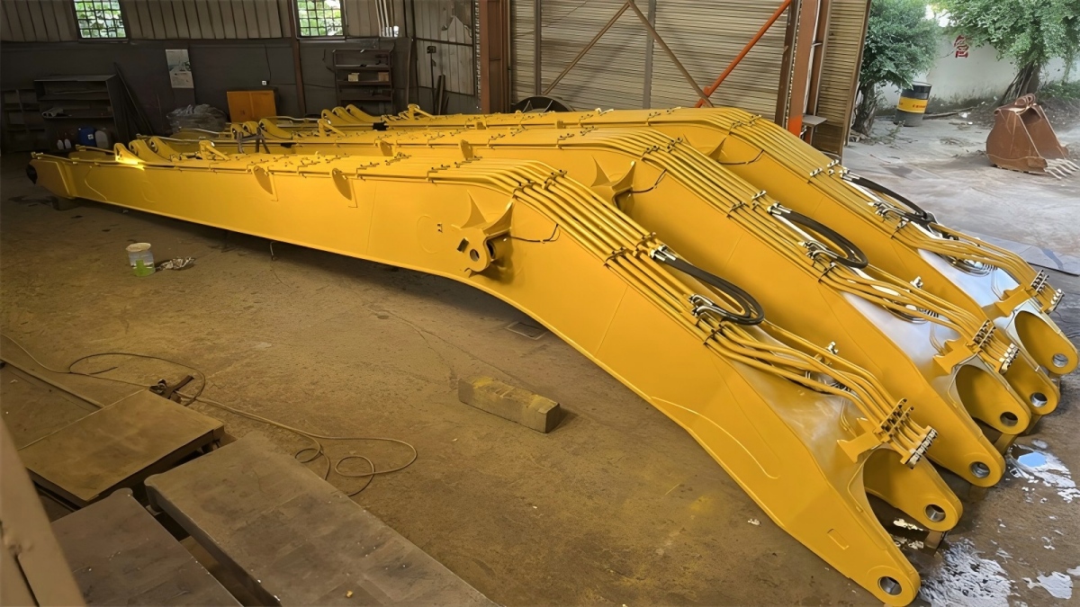
The long boom, a critical functional enhancement in the field of construction machinery, is widely used in challenging scenarios such as deep foundation excavation, river dredging, and mining operations. Its performance parameters directly determine equipment efficiency, safety, and cost-effectiveness. Focusing on the core theme of "excavator long boom performance," this article systematically explores its technical essence and decision-making logic through three dimensions—length selection, load capacity, and stability impact—integrating material science, engineering mechanics, and real-world applications to provide a scientific foundation for procurement and retrofitting.
I. Length Selection: Balancing Operational Scenarios and Engineering Mechanics
1.1 Length Classification and Typical Applications
long booms typically range from 6 to 24 meters, categorized as follows:
Short Booms (6–9 meters): Ideal for general earthwork and municipal pipeline installation, balancing digging depth (4–6 meters) and mobility.
Medium-Long Booms (9–15 meters): Used for deep foundation pits (8–12 meters) and river dredging, requiring reinforced hydraulic systems.
Ultra-Long Booms (15+ meters): Designed for mining bench leveling, reservoir slope protection, and other ultra-deep (15+ meters) or long-reach operations.
Case Comparisons:
Komatsu PC300-8 with 12-meter Boom: Achieves a digging depth of 10 meters in deep foundation pits but increases cycle time by 25% compared to standard booms.
Caterpillar 336F with 18-meter Boom: Extends operational radius to 22 meters in mining but requires an additional 3 tons of counterweight.
1.2 Mathematical Relationship Between Length and Digging Performance
Key parameters can be quantified using the following formula:
Maximum Digging Force (FF):
F=P×AL×ηF=LP×A×η
PP: Hydraulic system working pressure (MPa)
AA: Effective cylinder area (mm²)
LL: Boom length (meters)
ηη: Mechanical efficiency (typically 0.8–0.9)
Example: For a boom with 25 MPa pressure, 7854 mm² cylinder area (φ100 mm diameter), and 12-meter length:
F=25×785412×0.85≈13.9 kNF=1225×7854×0.85≈13.9 kN
Compared to a 9-meter standard boom (F≈18.5 kNF≈18.5 kN), the digging force decreases by 25%, reflecting the "lever effect" amplification with increased length.
1.3 Decision-Making Model for Length Selection
A four-step approach is recommended:
Site Survey: Measure target digging depth (DD) and horizontal radius (RR), using R=L2−D2R=L2−D2 to derive required length.
Equipment Capability Verification: Confirm engine power and hydraulic flow meet long boom demands (Power=P×Q/600Power=P×Q/600, where QQ is flow in L/min).
Cost-Benefit Analysis: Compare procurement costs and fuel consumption increases (15–30% higher for long booms).
Risk Mitigation: Mandatory installation of tilt sensors and overload alarms for ultra-long booms (>15 meters).
II. Load Capacity: Material Strength and Structural Design Limits
2.1 Key Factors Influencing Load Capacity
Material Strength: Q345B (yield strength 345 MPa) or HG785 (785 MPa high-strength steel) are standard; the latter improves bending resistance by 30%.
Cross-Section Design: Box structures (4x higher torsional resistance vs. I-beams) are industry standard; advanced models use tapered sections (20 mm thick at the base, thinning to 12 mm at the tip).
Welding Quality: CO₂ gas shielded welding must achieve ≥90% base metal strength, verified via ultrasonic testing (UT).
Ultimate Load Test Data:
|
Boom Length (m) |
Material |
Max Load (tons) |
Failure Mode |
|
12 |
Q345B |
8.5 |
Root weld cracking |
|
12 |
HG785 |
11.2 |
Mid-section buckling |
|
18 |
HG785 + Stiffeners |
7.8 |
Cylinder mount deformation |
2.2 Dynamic Loads and Fatigue Life
long booms endure cyclic loads; fatigue life is estimated via Miner’s Linear Damage Rule:
∑niNi≤1∑Nini≤1
nini: Actual cycles under stress level ii
NiNi: Allowable cycles at stress level ii
Field Data: A 12-meter boom in quarry operations (40% impact loads) showed a fatigue life of 12,000 hours, 33% below theoretical values (18,000 hours), highlighting工况 impact.
2.3 Innovations in Load Capacity Enhancement
Composite Structures: Sany Heavy Industry’s latest booms embed 7075 aerospace aluminum (572 MPa tensile strength) in stress-concentration zones, reducing weight by 15% while improving stiffness.
Smart Stress Monitoring: XCMG integrates fiber Bragg grating sensors (±1 με accuracy) for real-time stress tracking and overload warnings.
III. Stability Impact: Center of Gravity Control and Anti-Tipping Design
3.1 Stability Quantification
Static Stability Factor (KK):
K=MAnti-TipMTip≥1.5 (per ISO 12117)K=MTipMAnti-Tip≥1.5 (per ISO 12117)
MAnti-TipMAnti-Tip: Stabilizing moment from counterweight and chassis
MTipMTip: Unbalanced moment from boom load and self-weight
Example Calculation:
For a Caterpillar 320GC (22-ton chassis, 5.2-ton counterweight) with a 15-meter boom (2.8-ton self-weight, 1.5-ton tip load):
K=62.6/43.5≈1.44<1.5⇒ Requires additional counterweight!K=62.6/43.5≈1.44<1.5⇒ Requires additional counterweight!
3.2 Stability Optimization Strategies
Counterweight Adjustment: Increase 200–300 kg per meter of added boom length (empirical rule). Volvo EC380D’s 12-meter boom raised counterweight from 6.3 to 7.1 tons.
Operational Limits: Kobelco SK350LC-10’s intelligent system restricts swing speed (≤5 rpm) and maximum tilt angle (≤45°).
Chassis Modifications: Liebherr R 976 Litronic offers widened tracks (800 mm → 1000 mm), boosting lateral stability by 30%.
3.3 Lessons from Tipping Incidents
Case Study: A 2022 incident involving an 18-meter boom on soft ground caused a tip-over. Analysis revealed:
Actual stability factor: 1.2 (far below the 1.5 threshold).
Hydraulic oil leakage led to $200k+ losses.
Key Takeaway: Strictly enforce "length-counterweight-ground bearing capacity" verification.
IV. Extended Performance Parameters: Holistic Considerations
4.1 Hydraulic System Compatibility
Flow-Pressure Curve: Maintain ≥90% rated pressure at full extension (e.g., Kawasaki K3V112DT pumps require +10 L/min reserve flow for 20-meter booms).
Thermal Management: Limit hydraulic oil temperature rise to ΔT ≤40°C via enlarged radiators or auxiliary cooling.
4.2 Environmental Adaptability
Cold-Start Performance: Use Low-VI oil (viscosity index ≥150) and electric heating jackets (≥500 W/m) for -25°C operations.
Corrosion Resistance: Coastal applications require C5-MAnti-corrosion grade (720-hour salt spray test), achievable via hot-dip galvanizing (≥80 μm coating).
4.3 Maintenance Economics
MTBF (Mean Time Between Failures): High-quality booms achieve ≥8,000 hours; inferior products may fail within 3,000 hours.
LCC (Life Cycle Cost): Includes procurement, fuel, maintenance, and downtime. A 12-meter boom’s 10-year LCC is ~2.3x its initial cost.
V. Performance Validation and Standards
5.1 Laboratory Testing Protocols
Strength Test: Apply 150% rated load per ISO 10987 for 1 hour (no permanent deformation).
Fatigue Test: Simulate 500k cycles (30–80% load range) with ≤2 mm weld cracks.
5.2 Field Performance Monitoring
GNSS + Tilt Sensors: Sany’s Smart Mining System tracks boom posture (±0.1° accuracy).
Hydraulic Pressure Analysis: Frequency >50 Hz indicates pin loosening.
Optimizing excavator long boom performance requires balancing length, load capacity, and stability. Future advancements in composites and digital twins will drive trends toward lightweight, intelligent, and high-reliability designs. Users should prioritize suppliers offering full-parameter test reports and digital maintenance services, while conducting on-site load tests to validate performance claims—ensuring minimized risks and maximized ROI.
Contact us for more information //www.dewandaparts.com/
How to choose the best excavator bucket ?
The compatibility and model matching issues of the extended arm of an excavator